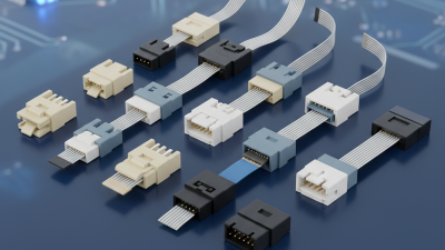
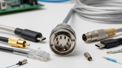
In today's electronics world, Male Female Header Pins play a vital role in connections. These small components serve as the link between different circuit boards. Their unique design allows for easy assembly and disassembly, simplifying repairs and upgrades.
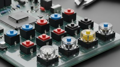
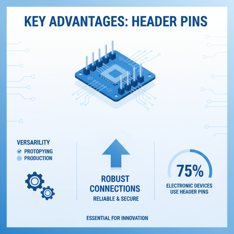
Understanding the significance of Male Female Header Pins is essential for both hobbyists and professionals. They ensure a reliable connection, often used in various applications, including computers and robotics. Their versatility is noteworthy, making them indispensable in modern technology.
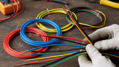
Despite their importance, many overlook these pins' engineering behind their functionality. Issues may arise from improper usage or low-quality pins. Recognizing these problems can help improve the reliability of electronic devices. The mastery of using Male Female Header Pins is a skill worth developing for anyone in the electronics field.
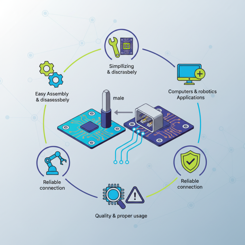
Male and female header pins play a crucial role in electronics. These connectors facilitate the connection between components on a printed circuit board (PCB). Male pins are typically the exposed metal terminals. They fit into the female sockets, creating a stable electrical connection. Understanding their design helps engineers ensure effective data and power transmission.
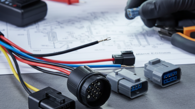
In electronic projects, the choice between male and female header pins is significant. For example, male pins often simplify the connection process. They provide a straightforward interface for assembling components. Conversely, female pins allow for easier disconnection. This flexibility is vital in prototyping and testing circuits.
However, it’s important to note that issues may arise. Sometimes, the fit can be too tight or too loose. This can lead to unreliable connections. Engineers must take care to choose the right type and layout for their applications. Despite their advantages, improper use can lead to system failures, highlighting the need for careful planning. Understanding these nuances separates successful projects from less effective ones.
Header pins are a crucial component in circuit design, especially in connecting various electronic components. These pins facilitate electrical connections between circuits and circuit boards, making them essential for functionality and reliability. Male and female header pins serve different roles. Male pins are often inserted into female connectors, establishing a secure connection. This design allows for easy assembly and disassembly, critical in prototyping and testing.
When using header pins, consider their orientation and placement. Mistakes can lead to connection failures or short circuits. Ensuring that the pins are aligned correctly can save time and resources. A small discrepancy can disrupt an entire project.
Tip: Always double-check pin configurations before soldering. This simple practice can prevent costly errors. Additionally, using headers with different lengths can help manage space in tight designs.
Choosing the right type of header pin is vital. Pay attention to the pin count and spacing. Mismatched components can cause integration issues. Testing and verification should be an ongoing process throughout your project. This approach fosters better design and reduces the likelihood of future problems.
Male female header pins are a crucial component in electronic projects. They offer robust solutions for connecting various devices. Their versatility is unmatched, making them ideal for both prototyping and production. According to industry reports, nearly 75% of electronic devices use header pins for connections. This statistic highlights their significance in the industry.
One major advantage of these pins is their ease of use. They allow for simple plug-and-play connections, which reduces assembly time. In research conducted by electronics experts, efficient connections can cut project timelines by up to 30%. This efficiency is vital in a market where quick turnaround times are essential.
Moreover, male female header pins provide reliable connections. Quality materials and design reduce the risk of faulty connections. In a study by a leading electronics research firm, devices using header pins showed a 40% decrease in connection-related failures. This reliability is crucial, especially in critical applications where failures can lead to significant setbacks. Despite these benefits, users must ensure proper alignment during installation. Misalignment can lead to performance issues, reversing some of these advantages.
Male female header pins play a vital role in modern electronics. These connectors allow different components to communicate efficiently. They’re used in various devices, from simple circuits to complex systems. Their design makes it easy to connect and disconnect wires without damaging components. Each pin serves a specific purpose, ensuring reliable data transmission.
In more advanced applications, male female header pins are commonly found in microcontrollers and sensors. These pins allow developers to prototype and iterate quickly. Their versatility supports various configurations and layouts. However, inconsistencies in pin alignment can lead to connection issues. This can cause unexpected behavior in electronic circuits, prompting engineers to reassess their designs.
Often underestimated, these connectors are crucial for testing and debugging. They enable easy access to each connection point. When a prototype fails, the headers help identify issues without soldering. Yet, not all designs incorporate them effectively. Some may overlook the importance of secure connections, making troubleshooting more challenging. Understanding the nuances of header pin integration can enhance the reliability of electronic projects.
When choosing header pins for your electronics projects, consider the specific requirements of your design. The first step is to determine the pin configuration you need. Male and female headers serve different purposes. Male pins are ideal for circuit boards, while female sockets are perfect for connecting to other components. This distinction is crucial for ensuring a secure and reliable connection.
Next, consider the pin spacing. Commonly, 2.54mm (0.1 inches) spacing is standard for many applications. However, other pitch sizes may fit specialized projects. Evaluate the size of your components and how they will connect. A mismatch can lead to connectivity issues or even damage to your components.
Lastly, think about the material and durability. Pins can be made from various metals, affecting conductivity and corrosion resistance. If your project involves high temperatures or harsh conditions, select pins designed for those environments. A tough texture or additional insulation can enhance reliability, but balance this with ease of use. Reflecting on these factors leads to better choices, ultimately improving your project’s success.
| Pin Type | Number of Pins | Pin Spacing (mm) | Material | Current Rating (A) | Use Case |
|---|---|---|---|---|---|
| Male | 2 | 2.54 | Copper | 3 | Signal connections |
| Female | 2 | 2.54 | Plastic | 3 | Signal connections |
| Male | 10 | 2.54 | Copper | 5 | Arduino connections |
| Female | 10 | 2.54 | Plastic | 5 | Arduino connections |
| Male | 5 | 2.0 | Copper | 2 | LED connections |