How to Choose the Right Board Wire for Your Needs?
Choosing the right Board Wire is not just a matter of matching a connector. Wire gauge, insulation, current, voltage drop, temperature, and bend radius all affect performance. A cable that fits neatly may still run too hot under sustained load. Small details matter.
The International Energy Agency’s Global EV Outlook 2024 reports nearly 14 million electric cars were sold worldwide in 2023, around 18% of total car sales. That figure does not prescribe a wire specification. It does illustrate how quickly electronic systems are expanding in demanding applications, where reliable connections matter. IPC-2221, an industry design standard for printed boards, offers useful guidance on electrical and mechanical design, but each wire assembly still needs to be checked against its own operating conditions.
Start with the actual load, not a guess based on appearance. Confirm the wire’s rated current and temperature, then account for voltage drop, insulation compatibility, connector pitch, vibration, and available routing space. Review the manufacturer’s datasheet and validate the assembly under realistic operating conditions. A short bench test can reveal heating or movement that a drawing misses. And specs can mislead. They describe defined test conditions, not every enclosure, airflow pattern, or installation. This guide will explain how to compare Board Wire options, ask suppliers precise questions, and avoid choices that look suitable but fail in service.
What Board Wire Is and How It Is Used
Board wire is the insulated conductor that carries power or signals to, from, or between circuit boards. It may connect a board to a switch, sensor, motor, battery, or another board. Unlike copper traces etched onto a PCB, wire can be routed around obstacles or replaced during repair. Small details matter. Wire gauge affects resistance and heat; insulation must suit the circuit’s voltage and operating temperature. Solid wire holds its shape, while stranded wire bends more easily and tolerates movement better.
Choose wire by checking current, voltage, temperature, length, and expected vibration. A long, thin conductor can cause voltage drop, even when the circuit works on the bench. For example, a power lead beside a warm motor needs suitable insulation and enough copper for its load. Signal wires may need careful routing to reduce interference. Secure connections with a suitable crimp or solder joint, then protect them from sharp board edges. In practice, a clean-looking installation can still hide a loose connection.
The scale of board production makes these choices consequential. Grand View Research estimated the global printed circuit board market at USD 73.4 billion in 2023, with projected growth through 2030. That figure describes boards, not wire, but it signals how widely board-level connections are used. Check the board documentation and component requirements before selecting wire; a familiar gauge is not automatically the right one. For safety-critical designs, have the current and temperature calculations reviewed by a qualified engineer.
Common Board Wire Types and Their Key Properties
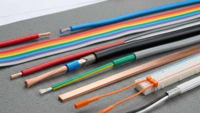
Common board wire types differ in flexibility, space needs, and current handling. Solid-core wire holds its shape and fits stable, low-vibration connections. Stranded wire bends more easily, making it useful for moving assemblies or tight routing. Ribbon cable keeps multiple conductors flat and organized, but its width can limit placement. Small detail: insulation matters too.
Copper remains common because it conducts well. The International Annealed Copper Standard sets reference copper conductivity at 100% IACS, or about 58 MS/m at 20°C. In practice, wire gauge, length, temperature, and insulation all affect performance. A short jumper may work at a current that would heat a longer, thinner lead. IPC-2152’s test-based ampacity charts likewise show that conductor dimensions and temperature rise must be considered together.
For board-level wiring, insulated hookup wire is often a practical choice; select solid or stranded conductors based on movement and assembly access. Check the wire’s rated temperature, voltage, and current, then verify clearances against the board layout. IPC/WHMA-A-620 provides workmanship criteria for cable and wire-harness assemblies, including crimped connections. Standards help, but they do not replace testing the actual assembly. I’d also leave room for inspection; cramped wiring can look acceptable until rework begins.
How to Define Your Electrical and Environmental Requirements
Start by defining what the wire must carry. Record the system voltage, normal current, and any brief startup surge. Note how long the wire run is and how it connects to the board. These details affect conductor size, voltage drop, and heat buildup. Small details matter. A wire that works on a short bench setup may behave differently inside a tightly packed enclosure. Check the board’s documentation and the wire’s technical data rather than relying on color or appearance.
Then describe the environment around the wire. Estimate the highest and lowest temperatures, and consider humidity, dust, vibration, and contact with oils or cleaning fluids. Match the insulation to those conditions, and check its temperature rating and flexibility. A wire routed past a warm component may need different insulation from one used in an open, cool case. Also consider movement: repeated bending near a connector can fatigue conductors over time. I’d leave room for routing and strain relief. It is easy to overestimate how neatly a first prototype will fit. A simple test under realistic operating conditions can expose problems that a drawing misses.
How to Compare Wire Gauge, Insulation, and Compatibility
Choosing board wire starts with the current it must carry, but gauge alone does not settle the question. A thicker conductor usually reduces resistance and voltage drop, yet it can crowd a compact board or strain a small terminal. Check the expected current, wire length, temperature, and whether several conductors share a bundle. A short test lead and a long power run may need different gauges. Measure the actual route, not just the straight-line distance.
Insulation matters just as much. Compare its temperature rating with the heat near components, and consider abrasion where wire passes an edge. Flexible insulation can ease tight bends, while thicker jackets may resist wear but take up precious space. Small details count. Compatibility is physical and electrical: confirm the conductor fits the connector, accepts the intended soldering method, and suits the board’s voltage and environment. Stranded wire bends easily; solid wire holds its shape but can be less forgiving after repeated movement. One detail is easy to miss.
Before settling on a choice, consult the wire and connector specifications, then inspect a sample in the real assembly. Check for loose strands, pinched insulation, and terminals that need force to close. A neat fit can still be wrong if the wire warms under load. Ratings also vary with installation conditions, so avoid treating a gauge chart as a universal answer. I would leave extra room for routing when possible; in practice, that space is often underestimated.
How to Choose the Right Board Wire for Your Needs
Compare Copper Wire Gauge by Resistance
Thicker wires have lower AWG numbers and lower resistance, which can help reduce voltage drop. Values shown are approximate copper conductor resistance at 20°C; actual performance varies with temperature and installation conditions. Choose insulation rated for the circuit’s voltage, temperature, and environment, and confirm that the wire gauge and conductor type are compatible with the board terminals.
How to Verify Your Board Wire Choice Before Installation
Before installation, match the wire to the drawing, connector, and actual operating conditions. Check conductor area, insulation temperature rating, voltage rating, and expected current. Then inspect a sample against the board: does it reach the terminal without tension, sharp bends, or contact with hot components? Fit matters. A wire that looks right on paper may not sit securely in the connector.
Use measurable checks, not color or appearance alone. IEC 60228 lists a maximum DC resistance of 18.1 ohms per kilometer at 20°C for a 1.0 mm², class 2 copper conductor. Measure a known wire length with suitable equipment and compare the result, allowing for instrument lead resistance and temperature. IPC-2152’s thermal design guidance also shows why current capacity depends on conductor geometry and temperature rise; board-trace guidance is not a direct wire rating. Do not guess. Verify continuity and polarity, then confirm that the termination holds as specified. Keep sensitive components disconnected before any insulation-resistance test. I still find the physical fit easy to underestimate, especially when a harness is installed in a crowded enclosure. A documented check helps catch that mistake before power is applied.