Why Choose Cable Wire Connectors for Your Projects?
Every electrical project depends on small connections that must perform quietly. Cable Wire Connectors join conductors securely, protect signal quality, and simplify future maintenance. Behind a control panel, a properly selected connector prevents loose wires, heat buildup, and costly downtime.
The market is expanding. Grand View Research reported that the global electrical connectors market was valued at approximately USD 84.6 billion in 2023. Its report projects continued growth through 2030, supported by electric vehicles, renewable energy, industrial automation, and data infrastructure. MarketsandMarkets also identifies rising vehicle electronics and advanced wiring systems as major demand drivers. These figures show opportunity, but they do not remove practical risks.
“The connector industry is a bellwether for the world economy,” says Dennis Zogbi, president of Bishop & Associates. His observation explains why connector choices deserve more attention than their compact size suggests. A reliable option should match wire gauge, current rating, insulation type, vibration exposure, and installation environment. Outdoor equipment may need sealing against moisture. Factory machinery may require strain relief and locking features. Tight spaces reward compact designs.
Still, no connector is perfect. A product can meet its datasheet and fail after careless crimping. That uncomfortable detail matters. Hands-on experience, verified specifications, and controlled testing should guide the final choice. Cable Wire Connectors are not merely joining parts. They are practical safeguards between design intent and real-world performance.
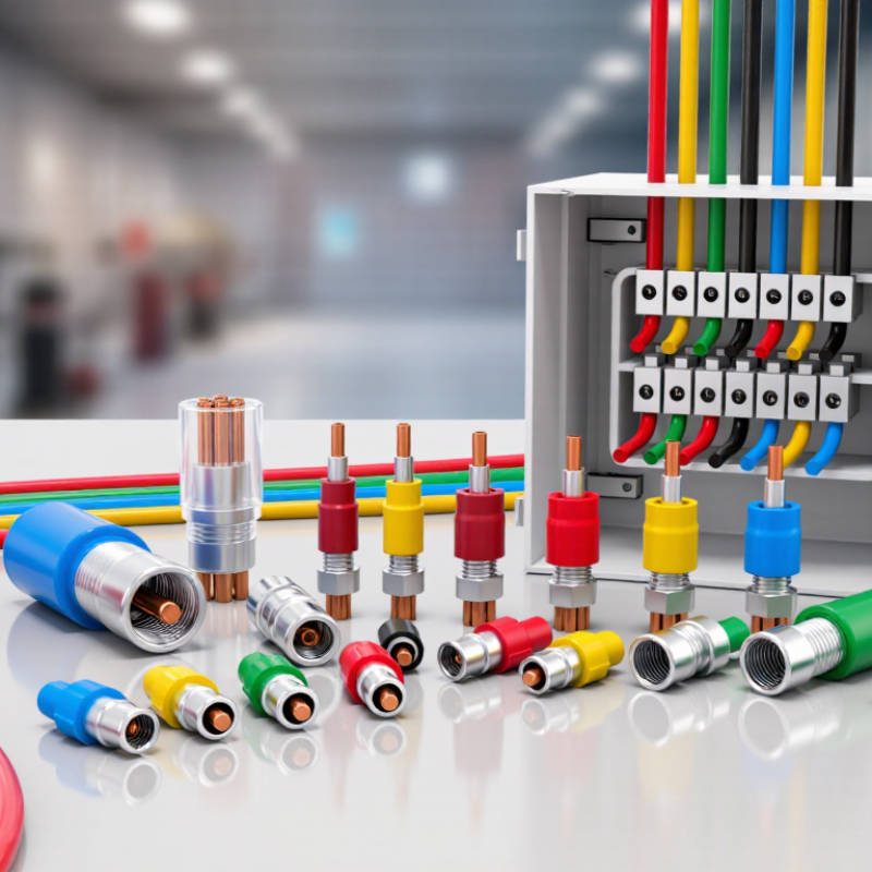
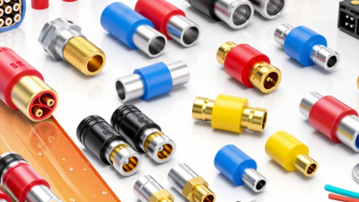
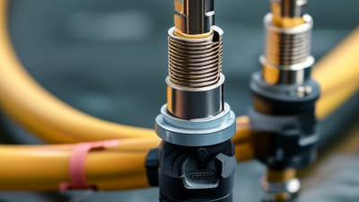
Cable wire connectors are compact components that join two or more electrical conductors. They create a continuous path for current between separate cable sections. Inside, a metal contact touches the stripped wire or terminal. An outer housing helps prevent accidental contact, movement, and moisture exposure. Some connectors use screws, while others use crimping, spring pressure, or locking tabs. They are small, but their mechanical grip matters.
A reliable connector matches the cable’s wire gauge and expected current. During installation, I inspect the conductor for clean copper and remove only the required insulation. Too much exposed wire can cause contact with nearby parts. Too little exposed wire may prevent a firm connection. A crimping tool compresses the terminal around the conductor, creating stable contact without relying on solder. Spring connectors apply constant pressure, even when small vibrations occur.
In practical projects, I gently pull each completed wire to check its retention. I also verify polarity and insulation before energizing a de-energized circuit. The connection matters. Heat, moisture, and repeated bending can weaken unsuitable parts. I once overlooked cable movement near a connector, and the strain became obvious later. That mistake changed my process: I now add strain relief and leave enough cable slack. A connector is not automatically safe because it looks secure. Its rating, installation quality, and surrounding conditions all require careful review.
Why Choose Cable Wire Connectors for Your Projects?
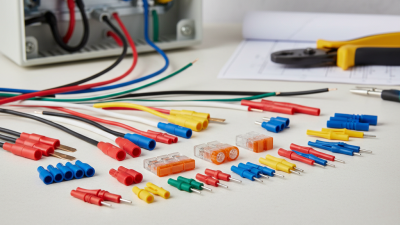
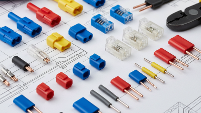
Different projects need different cable wire connectors. Indoor lighting often suits twist-on connectors for compatible copper conductors. They are quick, compact, and easy to inspect. For stranded wires, lever-style connectors can simplify installation. Check their rated wire sizes carefully. Not every model accepts every conductor.
Crimp connectors work well in vehicles, control panels, and areas exposed to vibration. A correctly sized terminal should grip the conductor firmly, not crush it. Butt connectors join two cables neatly. Heat-shrink versions add protection against moisture and abrasion. Outdoor lighting and garden equipment may need gel-filled or sealed connectors. These reduce water entry, but they still require proper cable preparation.
Terminal blocks suit junction boxes and equipment panels needing future maintenance. They keep multiple circuits organized and make testing easier. Larger cables may require mechanical lugs, especially in distribution work. Confirm conductor material, current rating, voltage rating, and temperature limits before installation. Mixed metals need connectors specifically approved for that combination. Follow local electrical requirements and the connector maker’s instructions.
I once trusted a connector because it felt tight. That was not enough. The wire later loosened under movement. A pull test, visual inspection, and correct tool would have exposed the problem earlier. Small details matter. Choose the connector for the environment, cable type, and expected load, not just its appearance.
Compare common cable wire connector types by installation method, conductor compatibility, environmental protection, and typical project suitability. Electrical ratings are representative of commonly available products; always confirm the connector manufacturer's specifications and local electrical codes before installation.
| Connector Type | Typical Conductor Range | Typical Voltage Rating | Typical Current Rating | Installation Method | Environmental Protection | Reusable? | Best-Suited Projects | Main Advantages | Important Limitations |
|---|---|---|---|---|---|---|---|---|---|
| Twist-On Wire Connector | Approximately 22–8 AWG (0.34–8.4 mm²), depending on the connector size; commonly used with solid or stranded copper conductors | Up to about 600 V | Determined by wire size and listed application | Strip the conductors, place them together, and twist the connector onto the wires | Generally intended for dry, enclosed locations unless specifically listed for damp or wet environments | Usually no; replacement is recommended after removal or damage | Residential lighting, junction boxes, control wiring, and general indoor splicing | Low cost, quick installation, compact size, and no separate crimping tool required | Connection quality depends on correct stripping, conductor combination, and tightening; not suitable for every vibration or moisture-prone application |
| Crimp Butt Splice Connector | Common sizes include 22–18, 16–14, and 12–10 AWG (0.34–6.0 mm²) | Typically 300–600 V, depending on construction and listing | Often up to approximately 15–30 A, depending on wire size and connector design | Insert stripped conductors into opposite ends and compress with the correct crimping tool | Standard versions suit dry areas; heat-shrink versions can provide moisture and strain protection when properly sealed | No; cutting and replacing is normally required | Automotive harnesses, appliance repairs, control panels, and permanent in-line cable splices | Strong mechanical retention, consistent results with the correct tool, and good resistance to vibration | Requires a suitable crimp tool; an incorrect crimp can cause high resistance, heating, or pullout |
| Heat-Shrink Waterproof Butt Splice | Commonly available for approximately 22–10 AWG (0.34–6.0 mm²) | Typically up to about 600 V, depending on product listing | Usually matched to the applicable conductor size | Crimp the splice, then heat the outer sleeve evenly until it seals around the insulation | Suitable for many outdoor, automotive, marine, and damp applications when fully sealed and correctly installed | No; intended as a permanent splice | Outdoor lighting, vehicle wiring, marine equipment, irrigation controls, and exposed cable repairs | Combines electrical connection, insulation, strain relief, and improved moisture resistance | Needs a heat source and correct heating technique; not suitable where the cable insulation cannot tolerate installation heat |
| Lever-Operated Spring Connector | Often approximately 24–12 AWG (0.2–4.0 mm²), with separate versions for solid, stranded, or mixed conductors | Commonly 300–450 V | Commonly up to approximately 20–32 A, depending on model and conductor size | Strip the wire, open the lever, insert the conductor, and close the lever | Generally for dry, enclosed locations unless specifically rated for damp or wet environments | Yes, when the connector remains undamaged and the manufacturer permits reuse | Lighting alterations, temporary installations, laboratory wiring, and projects requiring frequent inspection | Fast tool-free installation, visible conductor entry, easy maintenance, and compatibility with many conductor types | Usually larger than a basic twist-on connector; exposed use requires an appropriate enclosure |
| Screw Terminal Connector | Commonly approximately 22–10 AWG (0.34–6.0 mm²), depending on terminal size | Often 250–600 V | Frequently 10–30 A, depending on terminal construction and wire size | Insert the conductor into the terminal and tighten the screw to the specified torque | Usually for dry, enclosed equipment; specialized versions are available for harsher environments | Yes, provided the terminal and conductor remain undamaged | Control cabinets, test equipment, power supplies, low-volume prototypes, and serviceable wiring assemblies | Easy to inspect, disconnect, and reconnect; suitable for organized equipment wiring | Loose screws can create resistance and heat; stranded wires may require ferrules where specified |
| Barrier Strip or Terminal Block | Common ranges include 22–10 AWG or 18–4 AWG (0.34–25 mm²), depending on block size | Commonly 150–600 V | Approximately 10–50 A or higher for larger designs | Secure one or more conductors under screw clamps or spring terminals in a mounted block | Generally installed inside an enclosure; enclosed or sealed versions are available for specialized applications | Yes | Industrial control panels, distribution points, instrumentation, and multi-circuit service connections | Neat circuit organization, clear test points, expandable wiring, and straightforward maintenance | Requires mounting space and correct torque; exposed terminals must be protected against accidental contact |
| Insulated Ring or Fork Terminal | Commonly used with approximately 22–10 AWG (0.34–6.0 mm²) wire and matching stud sizes | Often up to about 600 V | Based primarily on conductor size and terminal construction | Crimp the terminal onto the wire, then fasten it to a threaded stud or screw terminal | Standard versions are for protected locations; sealed and corrosion-resistant versions are available | Usually no after crimping | Battery connections, grounding points, automotive wiring, power distribution, and equipment terminals | Reliable mechanical attachment and good resistance to accidental wire pullout; ring styles remain secured if the screw loosens slightly | Requires the correct terminal size, crimp tool, stud diameter, and available installation space |
| Push-In Spring Connector | Commonly approximately 22–12 AWG (0.34–4.0 mm²), often limited to specified solid or rigid stranded conductors | Often 300–450 V | Commonly up to approximately 15–20 A | Strip the conductor to the specified length and push it into the spring clamp opening | Usually intended for dry, enclosed electrical boxes or equipment | Some versions permit release; others are designed for one-time installation | Fast lighting installation, repetitive production wiring, and compact junction-box connections | Very fast installation, compact form, and consistent spring pressure when used with compatible conductors | Conductor type and strip length must match the product requirements; removal can be less convenient than lever-operated designs |
Note: Voltage and current ratings vary by conductor material, insulation temperature, connector design, installation method, ambient temperature, and applicable standards. Use only connectors listed for the intended wire type, size, environment, and circuit application.
Why Choose Cable Wire Connectors for Your Projects?
Cable wire connectors provide a practical way to join conductors securely and consistently. In workshop installations, a properly selected connector can reduce loose contacts, exposed wire, and unexpected maintenance. It also keeps connection points organized inside control boxes, junction areas, and equipment housings.
Their benefits extend beyond simple assembly. Many connectors provide strain relief, helping prevent a cable from pulling directly on its terminals. Sealed versions can limit moisture and dust around sensitive connections. This matters in outdoor lighting, industrial machinery, and vehicles. Correct sizing is essential. Check the wire gauge, current rating, voltage rating, temperature range, and environmental protection level before installation. A connector that feels strong may still be electrically unsuitable.
Cable wire connectors can also save service time. Technicians can disconnect sections without cutting every wire, which supports testing and repairs. I have found that clear labeling makes this advantage even greater. One overlooked detail is vibration. A connection may pass an initial test but loosen after repeated movement. Locking features and proper crimping help, though neither replaces inspection. Poorly prepared wire ends remain a weakness. In practice, installers should pull-test each finished connection and inspect for uneven crimps or exposed strands. The process takes minutes. It can prevent much longer troubleshooting later.
Cable wire connectors provide secure joining, easier maintenance, and protection against environmental conditions. The chart shows the two protection-code levels defined for representative IP ratings under IEC 60529.
The first digit indicates protection against solid objects or dust, while the second digit indicates protection against water. Higher numbers represent higher protection within each category. Actual connector performance depends on the complete assembly, installation method, and specified IP rating.
Reference: IEC 60529 ingress-protection code definitions.
Choosing the right cable wire connector begins with the electrical load, not the connector’s appearance. Check conductor size, current, voltage, and insulation diameter before comparing designs. The IEA’s Global EV Outlook 2024 estimated nearly 17 million electric car sales worldwide in 2024. This growth increases demand for reliable connections in vehicles, chargers, and control systems.
Match the connector to the working environment. Outdoor installations may require an enclosure rated under IEC 60529 for water and dust protection. High-temperature areas need materials that tolerate heat without softening or cracking. Vibration also matters. Crimp connectors can provide stable contact when the correct tool and die are used. Screw terminals allow inspection, but loose torque can create heat. Push-in designs save time, yet they may not suit every wire type. Measure twice.
Look for documented current ratings, temperature limits, and applicable test standards. IEC 60999-1 addresses safety requirements for screw-type clamping units, while UL 486A-486B covers many wire connectors and terminals. These references offer stronger evidence than a vague product description. A common mistake is selecting by wire gauge alone. Connector length, contact material, strand flexibility, and available installation space also affect performance. In field inspections, poor stripping often causes more trouble than the connector itself. Leave enough conductor length for a clean, full insertion. Fit matters. Recheck the connection after assembly, especially where vibration or thermal cycling is expected.
Why Choose Cable Wire Connectors for Your Projects?
How Should Cable Wire Connectors Be Installed Safely?
Cable wire connectors create a firm electrical and mechanical connection between conductors. They can simplify repairs, panel work, and equipment wiring when selected correctly. Safety begins before opening the package. Turn off the circuit breaker, lock it where possible, and verify the wires are dead with a properly rated meter. Do not rely only on a wall switch or a non-contact tester.
Check the connector’s size, conductor range, insulation type, and environmental rating. A connector that is too large may grip poorly. One that is too small can damage the wire. Strip only the specified length, keeping the copper clean and straight. No loose strands should remain outside the connector. For screw-type models, tighten to the manufacturer’s stated torque. Over-tightening can crush the conductor.
Make the connection.
After installation, pull each wire gently to confirm its grip. The cable should have strain relief, especially near vibrating equipment or moving enclosures. Keep connections dry unless the connector is rated for moisture. Inspect for cracked insulation, exposed copper, and crowded terminals before restoring power. In field work, I have seen rushed stripping cause later heating, even when the connection initially looked acceptable. I still recheck every termination under bright light. Local electrical rules may require a qualified electrician, particularly inside service panels or high-voltage equipment. When the fit feels uncertain, stop and verify the specification instead of forcing the connection.