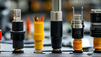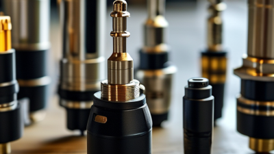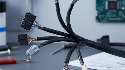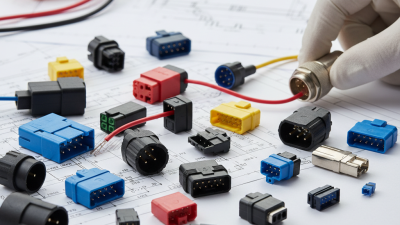
Wire Harness Connectors are small components with a demanding responsibility. They join wires, terminals, sensors, control units, and power systems. A connector must carry current, resist vibration, and protect electrical contact. It must also allow inspection and service inside cramped spaces.
The automotive wiring harness market shows why this subject matters. Fortune Business Insights valued the global market at approximately US$47.75 billion in 2023. Its report projects continued growth through 2032, driven by electric vehicles, advanced driver-assistance systems, and vehicle electronics. MarketsandMarkets also identifies lightweight materials, higher circuit density, and automated assembly as major development trends. These figures describe market direction, not guaranteed performance. Real reliability still depends on terminal design, sealing, crimp quality, and installation practice.
William J. Bishop, founder of Bishop & Associates, has described connectors as “the unsung heroes of electronics.” That phrase captures their hidden importance. A loose terminal can create heat, voltage loss, intermittent signals, or complete system failure. Engineers often focus on software and control modules. They may underestimate one poorly crimped contact. That is a mistake.
This guide explains how Wire Harness Connectors work, from current transfer to mechanical locking and environmental protection. It also examines connector types, materials, coding systems, testing methods, and common failure points. Some specifications appear simple. They are not. Small differences in contact force, plating thickness, or sealing pressure can change field performance. Reliable selection requires standards, test evidence, supplier experience, and careful application review.
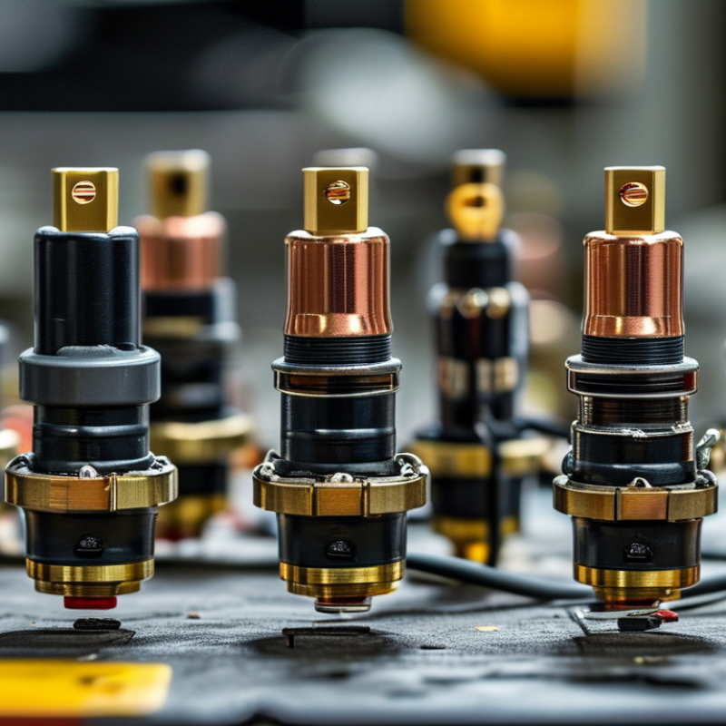
Wire harness connectors are the joining points that let electrical circuits work safely and consistently. A complete connector usually includes terminals, a housing, seals, and locks. Each part has a specific job.
Terminals carry current between wires and equipment. Their metal contact surfaces must fit tightly, but not so tightly that installation damages them.
The housing holds terminals in the correct positions and prevents accidental contact. It also guides assembly inside limited spaces.
Seals block water, dust, and oil from entering the connection. This matters in engine compartments, outdoor equipment, and areas exposed to vibration.
Primary locks hold terminals inside the housing. Secondary locks provide extra retention and show whether assembly is complete. A small click can be useful evidence, but it should not replace a visual inspection.
Tips:
Match the terminal size with the wire gauge and expected current. Check that insulation reaches the correct crimp position.
Pull each wire gently after crimping. If it moves, stop and inspect the connection.
Keep sealing surfaces clean and undamaged. Even a tiny twist can create a future failure.
In practical assembly work, connectors sometimes look secure while one terminal sits slightly backward. I have found this easy to miss when working quickly.
A continuity test and careful terminal-height check can reveal the problem. Moisture testing is also valuable, although it may not reproduce every real operating condition.
Wire harness connectors join wires to equipment, sensors, and power sources. They provide electrical continuity and allow easier installation or maintenance. Their design depends heavily on circuit count, current rating, and operating environment.
Circuit count means the number of separate electrical paths inside one connector. Low-count connectors suit simple sensors, lighting, or small control circuits. Higher-count versions support complex systems with limited installation space. However, more terminals can increase assembly difficulty. A crowded housing may also complicate inspection and repair.
Current rating shows how much electrical load each terminal can safely carry. Larger terminals and thicker wires usually support higher current. Never select a connector by terminal count alone. Check wire size, temperature rise, contact resistance, and expected duty cycle. Heat can reduce performance over time. Environmental conditions matter equally. Sealed connectors resist moisture, dust, and fluid exposure. Vibration-resistant designs help prevent intermittent faults. High-temperature applications need suitable housing and insulation materials.
Tips: Confirm the maximum current for every circuit, not only the average load. Check derating tables when several circuits operate together. Inspect locking features, terminal alignment, and sealing surfaces before installation. A practical mistake is ignoring service access. The connector may fit electrically, yet remain difficult to test or replace. Use clear circuit labels and verify each connection with a continuity check.
Wire harness connectors join electrical circuits through terminals that press against matching contacts. Their performance depends on contact force, not appearance alone. Adequate force keeps metal surfaces touching through vibration, dirt, and slight movement. This stable contact creates a low-resistance path for current.
When resistance rises, electrical energy becomes heat. A loose terminal may feel secure but develop hot spots during operation. Excessive force creates another problem. It can deform the terminal, damage its protective surface, or make future servicing difficult. In practical inspections, I check crimp shape, wire position, terminal retention, and signs of discoloration. Small details matter. Still, visual checks can miss microscopic oxidation or intermittent faults. That limitation deserves attention.
Tips: Use the specified wire size and a calibrated crimping tool. Pull the wire gently after crimping. Confirm that the terminal locks fully into the connector housing. Keep moisture away from exposed contacts. Do not force a misaligned connector. A controlled contact force supports dependable current transfer, while low resistance helps prevent unnecessary heating. Testing under realistic vibration and load is wiser than relying on a single continuity check.
Wire harness connectors join electrical circuits while protecting their terminals from movement, moisture, and contamination. In vehicles and industrial equipment, each connector must maintain stable contact despite vibration and temperature changes. According to IEC 60529, an IP67 connector is dust-tight and can withstand temporary immersion in water up to one meter for 30 minutes.
That rating matters in exposed wiring. Dust cannot enter the sealed enclosure during testing. Water also cannot reach the contacts under specified immersion conditions. However, IP67 does not automatically mean resistance to high-pressure washing, chemicals, saltwater, or repeated thermal cycling. That assumption is easy to regret. Seals can harden. Cables can pull.
A 2024 Grand View Research report estimated the global automotive wiring harness market at more than 50 billion US dollars, reflecting the growing need for dependable electrical connections. In practical installation, technicians should check the connector seal, terminal lock, cable strain relief, and mating alignment. A small gap can defeat the rating. Field experience also shows that damaged insulation often causes trouble before the connector housing fails. Test samples may pass immersion testing, yet poorly routed harnesses can still collect water at low points. Regular inspection remains necessary, especially near wheel wells, battery compartments, and outdoor control cabinets.
| Data Dimension | Specification or Function | How It Works in a Wire Harness | IP67 and Installation Relevance |
|---|---|---|---|
| Basic Definition | A wire harness connector is a separable electrical interface that joins wires, terminals, sensors, actuators, control units, or power devices. | Male and female connector halves align their terminals and create a detachable electrical and mechanical connection. | Sealed connector designs add environmental protection around the mating interface and cable entry. |
| Main Connector Parts | Typical parts include a housing, terminals, wire seals, interface seal, secondary lock, terminal position assurance device, and backshell or cable seal. | The housing positions the terminals, seals block contaminants, and locking devices prevent accidental separation or terminal back-out. | Every sealing element must be correctly installed; a missing seal or unlocked terminal can compromise the enclosure rating. |
| IP Code Meaning | IP67 is an ingress-protection rating defined by IEC 60529. | The first digit, 6, indicates complete protection against dust ingress. The second digit, 7, indicates protection against temporary immersion. | IP67 does not automatically indicate protection against high-pressure water jets, chemicals, salt spray, or permanent underwater operation. |
| Dust Protection | Dust-tight: no dust ingress is permitted under the applicable test conditions. | A sealed interface, correctly fitted wire seals, and a closed unused cavity prevent dust from reaching the contacts. | Dust protection helps reduce abrasive contamination, contact fouling, and insulation-surface tracking in dusty environments. |
| Water Immersion | Temporary immersion in water up to 1 meter for up to 30 minutes, under the IEC 60529 IPX7 test conditions. | Elastomeric seals and controlled mating geometry limit water penetration into the contact chamber. | The rating applies to the tested configuration. Cable exits, plugs, backshells, and mating conditions must remain properly sealed. |
| Contact Function | Terminals transfer electrical current and signals between the harness and the connected equipment. | Spring force at the terminal interface maintains electrical contact despite normal vibration and thermal cycling. | Contact material, plating, wire size, and temperature determine the allowable current and service life; there is no single current rating for all IP67 connectors. |
| Wire Termination | Common termination methods include crimping, soldering, and insulation-displacement technology. | A properly formed crimp creates a gas-tight connection between the conductor and terminal barrel without solder. | Crimp height, pull-out force, conductor strip length, and seal position should follow the applicable connector and terminal specifications. |
| Mechanical Locking | Primary locks, latches, threaded couplings, bayonet couplings, or lever locks hold the connector halves together. | The locking system maintains mating force and prevents separation caused by vibration, shock, or cable movement. | IP protection can be lost if the connector is not fully mated or if a latch is damaged. |
| Terminal Position Assurance | A secondary locking feature confirms that terminals are fully seated in the housing. | It helps prevent a terminal from moving backward when the connector halves are mated or when the harness is subjected to vibration. | Correct terminal seating is essential for both electrical reliability and consistent seal compression. |
| Wire Seal Function | Individual cable seals close the gap between the connector cavity and the insulated wire. | The seal is compressed around the cable jacket while the terminal remains electrically connected inside the cavity. | Incorrect wire diameter, damaged seals, or excessive stripping can create a leakage path. |
| Typical Applications | Automotive wiring, industrial equipment, outdoor lighting, agricultural machinery, construction equipment, marine-adjacent systems, and sensor assemblies. | The harness distributes power and signals while allowing modules or equipment to be assembled, serviced, or replaced. | Application conditions should be checked for temperature, vibration, UV exposure, chemicals, pressure washing, and immersion duration. |
| Environmental Limits | Environmental performance depends on the connector construction, sealing materials, terminal system, cable type, and testing method. | Materials are selected to withstand the expected combination of moisture, temperature variation, vibration, and contamination. | IP67 alone does not define operating temperature, electrical rating, chemical resistance, UV resistance, or mating-cycle durability. |
| Testing and Verification | Typical verification may include visual inspection, continuity testing, insulation-resistance testing, seal inspection, vibration testing, and ingress testing. | Tests confirm that the assembled harness maintains electrical continuity and environmental protection after mechanical or environmental exposure. | Testing should use the final connector, terminals, wires, seals, plugs, and assembly process intended for production. |
| Installation Checks | Inspect terminal seating, connector mating, secondary locks, wire routing, bend radius, strain relief, cavity plugs, and seal condition. | These checks prevent mechanical loads from being transferred directly to terminals or seals. | Do not use the connector as a handle or pull directly on wires; avoid sharp bends near the cable exit and replace damaged seals. |
| IP67 Limitation | IP67 is a defined ingress-protection test result, not a universal guarantee for every installation condition. | Real-world performance depends on assembly quality, aging, mating cycles, cable movement, contamination, and damage. | For continuous immersion, high-pressure washing, or severe chemical exposure, a higher or additional environmental specification may be required. |
| Reference basis: IEC 60529 ingress-protection designations. IP67 means dust-tight protection and temporary immersion protection up to 1 meter for up to 30 minutes under specified test conditions. Always confirm the connector assembly manufacturer's technical specification for electrical, mechanical, temperature, chemical, and durability ratings. | |||
Wire harness connectors join wires to sensors, control units, power devices, and grounds. Inside each connector, metal terminals create controlled electrical contact. Plastic housings maintain alignment, while locks prevent accidental separation. Seals help block water, dust, and road chemicals. Small details matter. A loose terminal can create heat, voltage loss, or an intermittent fault that appears only during vibration.
For vehicle harness development, USCAR-2 provides practical performance benchmarks for connector systems. Testing commonly examines terminal retention, mating force, temperature exposure, vibration, moisture, and contact resistance. ISO 19642 focuses on road-vehicle cables, including conductor construction, insulation, dimensions, and test conditions. These documents work together during design reviews, but they do not replace application-specific validation. A connector passing a laboratory test may still need testing beside an engine, battery enclosure, or moving door.
In 12–48 V vehicle systems, engineers must match terminal size, conductor area, fuse rating, and expected current. At 48 V, arcing behavior and insulation margins deserve closer attention, especially during switching or fault conditions. Voltage drop should be measured across the complete path, not only at the connector bench. In practical harness reviews, drawings often look correct while crimp height, seal compression, or cavity position remains uncertain. That is where rework begins. I would also avoid assuming one connector family suits every circuit; low-current signals, motor loads, and exposed chassis connections demand different mechanical and electrical evidence.