Leave Your Message

What Is an Electrical Pin and How Does It Work?

An Electrical Pin is a small conductive contact, but its job is far more important than its size suggests. It transfers power or signals between mating components, such as a wire, socket, printed circuit board, or connector housing. Inside a connector, the pin must maintain stable contact pressure while resisting vibration, heat, moisture, and repeated mating cycles.

Dr. Eric Bogatin, a respected signal-integrity engineer, often stresses this practical principle: “The interconnect is part of the circuit.” That idea explains why an Electrical Pin cannot be treated as a simple metal rod. Its material, diameter, shape, plating, and spacing all influence electrical performance. Copper alloys provide conductivity and spring strength. Gold, tin, or nickel plating can reduce oxidation and improve contact reliability. Even a thin layer of contamination may increase resistance.

The working process is straightforward. A mating socket receives the pin, applies controlled mechanical force, and creates a continuous conductive path. Current then moves through the contact interface. Signal quality depends on more than continuity. Impedance changes, contact resistance, heat, and mechanical movement can affect the result.

Small details matter.

In practice, engineers test pins under real conditions, not only in clean laboratories. They examine insertion force, temperature rise, corrosion, and wear after repeated cycles. Some designs still fail earlier than expected. That uncomfortable possibility deserves attention. A well-designed Electrical Pin is reliable, but no contact remains perfect forever. Understanding its structure and limitations helps engineers choose safer, longer-lasting connector solutions.
What Is an Electrical Pin and How Does It Work?

Definition and Basic Structure of an Electrical Pin

An electrical pin is a conductive contact that carries power or signals between connected parts. It usually appears as a narrow metal rod, blade, or plated surface. The pin enters a matching socket or touches another contact. This creates a controlled electrical path.

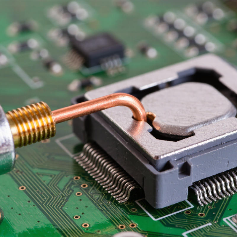
Its basic structure has three functional areas: the contact tip, the conductive body, and the termination end. The tip makes physical contact with the mating surface. The body carries current through a metal such as copper or an appropriate alloy. The termination end connects to a wire, circuit board, or internal component. A thin surface coating can improve conductivity and reduce corrosion. Small does not mean simple.

An electrical pin works through pressure, alignment, and continuity. Spring force may hold the pin firmly against its counterpart, even when the equipment moves slightly. The surrounding insulator keeps nearby pins separated and helps prevent accidental contact. During inspection, technicians often check for bent tips, loose joints, dirt, and damaged plating. These details can cause resistance, heat, or intermittent signals. The term “pin” is not perfectly precise; some designs use flat contacts or flexible beams instead. A technical drawing should confirm its shape, spacing, rated current, and connection method before assembly.񎟂

What Is an Electrical Pin and How Does It Work? - Definition and Basic Structure of an Electrical Pin

An electrical pin is a conductive contact used to transfer electrical current or signals between components, wires, circuit boards, connectors, or test equipment. The values below are representative engineering references; actual specifications depend on the application, connector design, material, and operating environment.

Dimension / Feature Definition Typical Reference Data How It Works or Why It Matters
Electrical function A conductive contact that carries power, signals, or reference potential. Used for power, ground, analog signals, digital signals, and measurement connections. The pin creates a low-resistance electrical path when it mates with a socket, pad, terminal, or test point.
Contact tip The mating end that touches another conductive surface. May be flat, rounded, tapered, fork-shaped, spring-loaded, or compliant. Its shape controls alignment, contact pressure, insertion force, and resistance to mechanical damage.
Contact body The main conductive section between the mating area and the termination area. Common base materials include copper alloys such as brass or phosphor bronze. Provides the current path and determines much of the pin's electrical resistance and mechanical strength.
Termination end The end connected to a wire, printed circuit board, crimp barrel, solder joint, or mounting hole. Common forms include solder tails, crimp sections, press-fit sections, wire-wrap posts, and PCB leads. Transfers current from the pin into the connected conductor or circuit structure.
Base material The metal used to form the pin and provide mechanical and electrical performance. Copper alloys are common because copper has high electrical conductivity and can be formed accurately. The alloy balances conductivity, spring force, fatigue resistance, hardness, and manufacturability.
Surface plating A protective conductive coating applied to the contact surface. Tin is common for economical connections; nickel may serve as a barrier layer; gold is used where low and stable contact resistance is important. Plating reduces oxidation, improves wear resistance, and helps maintain reliable contact over time.
Pin diameter or width The cross-sectional size of the conductive pin. Common connector pin sizes range approximately from 0.5 mm to 2.5 mm, although miniature and high-current designs may fall outside this range. Larger cross-sections generally support higher current and greater mechanical strength, while smaller sizes save space.
Contact resistance The resistance introduced at the pin-to-contact interface. Well-designed connector contacts are often specified in the milliohm range; the exact limit is application-specific. Lower resistance reduces voltage drop and heat generation, improving efficiency and signal integrity.
Current capacity The maximum current a pin can carry under defined thermal and environmental conditions. Small signal pins may carry less than 1 A, while larger power contacts can carry several amperes or more. Current capacity depends on pin size, temperature rise, contact resistance, spacing, cooling, and conductor size.
Voltage rating The maximum working voltage permitted between adjacent contacts or between a contact and ground. Ratings vary from low-voltage electronic circuits to much higher values in specialized power connectors. The rating is controlled by insulation thickness, spacing, creepage distance, clearance, and the surrounding environment.
Contact force The mechanical force pressing the pin against its mating contact. Typically measured in newtons; the acceptable value depends on the contact geometry and connector size. Adequate force maintains a stable electrical connection, while excessive force increases wear and insertion effort.
Pitch The center-to-center distance between neighboring pins in an array. Common board-level pitches include 2.54 mm, 2.00 mm, 1.27 mm, and 1.00 mm. Pitch determines component density, mating compatibility, insulation spacing, and routing space on a circuit board.
Insulating support The nonconductive material that holds one or more pins in position. Engineering thermoplastics and other electrical insulating materials are commonly used. The insulator prevents short circuits, maintains alignment, and provides mechanical support.
Spring or compliant section A flexible portion that compensates for tolerance, vibration, or surface variation. Used in spring pins, pogo pins, compliant press-fit pins, and flexible connector contacts. It maintains contact pressure even when the mating surfaces move slightly or are not perfectly aligned.
Common pin types Different pin constructions designed for specific connection methods. Solid pins, header pins, crimp pins, solder pins, press-fit pins, spring-loaded pins, and test pins. The selected type affects installation method, reusability, durability, current capacity, and serviceability.
Typical failure causes Conditions that cause intermittent or high-resistance connections. Oxidation, contamination, excessive insertion cycles, overcurrent heating, mechanical deformation, and poor termination. These conditions can increase resistance, cause voltage drop, create heat, or interrupt power and signal transmission.
Technical note: Electrical pin ratings are not universal. Always verify the applicable connector drawing, electrical standard, temperature limits, mating-cycle requirements, and safety clearance before selecting or using a pin.

Key Functions and Operating Principles of Electrical Pins

What Is an Electrical Pin and How Does It Work?

Key Functions and Operating Principles of Electrical Pins

An electrical pin is a small conductive contact that transfers power or signals between connected components. You can find pins in connectors, circuit boards, sensors, and test equipment. Their main functions include carrying current, maintaining signal continuity, and providing a stable mechanical connection. A pin usually contains a conductive metal core and a protective surface finish. The core carries electricity, while the finish helps resist corrosion and wear.

When two mating contacts meet, spring force pushes their surfaces together. This pressure reduces tiny air gaps and creates a dependable electrical path. Low contact resistance is important, especially in circuits carrying sensitive signals or higher current. A loose, bent, or contaminated pin may cause voltage drops, flickering signals, or unexpected heat. In practical bench testing, gently measuring continuity and resistance can reveal problems quickly. I once blamed a damaged cable, but a slightly misaligned pin caused the failure. That mistake reminded me to inspect the contact area first.

Tips: Keep pins clean and aligned. Never force a connector into place. Use appropriate test equipment and disconnect power before inspection. Check for discoloration, looseness, or deformation. Contact design is not always perfect, so verify performance under real temperature and vibration conditions.

What Is an Electrical Pin and How Does It Work?

Contact voltage drop increases with current and pin resistance according to Ohm’s law: V = I × R.

An electrical pin is a conductive contact that transfers power or signals between connected components. When current flows through the pin, its electrical resistance produces a small voltage drop and heat. Lower-resistance pins provide more efficient power transfer, while secure mechanical contact helps maintain stable conductivity during operation.

How Electrical Pins Establish and Maintain Connections

What Is an Electrical Pin and How Does It Work?

How Electrical Pins Establish and Maintain Connections

An electrical pin is a conductive contact that joins one circuit to another. It usually fits into a socket, terminal, or matching contact. During insertion, the pin meets a spring-like contact surface. This pressure creates a stable metal-to-metal path for current or signals. A properly designed pin also resists movement, heat, and repeated connection cycles.

Connection quality depends on more than physical contact. Contact force helps break through small surface films and limits resistance. Clean surfaces support better performance. However, dust, oxidation, vibration, and thermal expansion can weaken the connection over time. In practical inspections, a pin may look correctly seated while carrying an unstable signal. That detail is easy to miss. Engineers should check alignment, retention, contact wear, and temperature rise under normal load. A small design mistake can create intermittent faults.

Tips: Switch power off before inspection. Check for bent pins, loose retention, discoloration, or damaged insulation. Use the specified contact cleaner only when suitable. Do not force a tight connection. Measuring continuity alone may not reveal failures under vibration or load. I once underestimated mechanical stress during testing; that was a useful reminder. Electrical pins need both a reliable contact surface and controlled physical support.

Common Types and Applications of Electrical Pins

What Is an Electrical Pin and How Does It Work?

Electrical pins are small conductive contacts that transfer current or signals between components. A pin usually enters a matching socket, pad, or terminal. Its spring force or friction keeps the connection stable during operation. Contact pressure, metal quality, spacing, and alignment all affect performance.

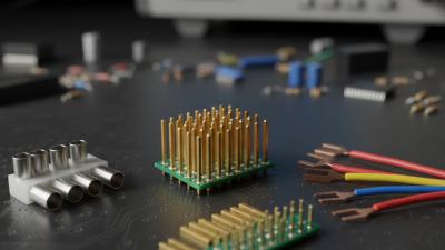
Common types include header pins, terminal pins, pogo pins, and crimp pins. Header pins connect circuit boards through fixed rows, often with precise spacing. Pogo pins contain a spring-loaded tip, making them useful for battery contacts, charging docks, and test fixtures. Terminal pins secure wires inside housings, while crimp pins provide firm wire-to-contact connections. These parts appear in control panels, sensors, computers, measurement equipment, and compact consumer devices. Small differences matter. A loose pin can create heat, noise, or intermittent signals.

Tips: Select a pin according to current, voltage, pitch, temperature, and mating cycles. Keep contact surfaces clean and avoid bending during assembly. I have seen alignment errors damage otherwise reliable connectors. That detail is easy to overlook. Check the drawing, inspect the finished joint, and test continuity under gentle movement. No design is perfect. Allowing service access can make future repairs far easier.

Design Factors, Materials, and Safety Considerations

An electrical pin is a conductive contact that transfers current between mating components. Its diameter, length, spacing, and insertion force shape performance. A pin that is too thin may overheat. A pin that is too tight may damage its socket. In practical design reviews, contact geometry often receives less attention than voltage ratings. That is a mistake.

Copper alloys provide strong conductivity and mechanical resilience. Tin plating supports economical connections, while nickel or gold finishes resist oxidation in demanding environments. Material choice depends on current, temperature, vibration, and mating cycles. IEC 60512 test methods evaluate contact resistance, mechanical strength, and environmental durability. Designers should test real assemblies, not only isolated pins. Small tolerances matter.

Safety begins with insulation distance and controlled heating. Engineers should check creepage, clearance, touch protection, and short-circuit behavior under abnormal conditions. IEC 61984 addresses connector safety requirements for many industrial applications. The 2024 Global E-waste Monitor reported 62 million tonnes of electronic waste in 2022, with only 22.3% formally recycled. That figure makes material recovery important during pin selection. Plated metals improve reliability, but mixed materials can complicate recycling. I have seen designs that passed initial testing yet failed after repeated thermal cycling. More verification is usually needed.