What Is an Electrical Pin and How Does It Work?
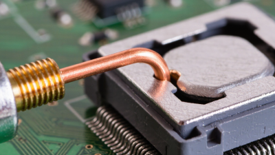
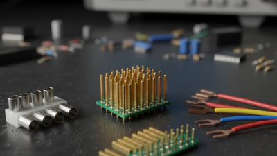
An Electrical Pin is a small conductive contact that carries power, signals, or both between connected components. It may appear inside a plug, socket, circuit board, relay, sensor, or wire-to-wire connector. Despite its size, the pin determines how reliably electricity travels through the connection. A loose or contaminated contact can create resistance, heat, intermittent signals, or complete failure.
Small part. Big job.
Most electrical pins use copper alloys with protective plating, such as tin, nickel, or gold. The base material provides conductivity and mechanical strength, while the plating helps resist corrosion and repeated wear. When a plug enters its matching socket, spring force keeps the pin pressed against the contact surface. This pressure creates a stable electrical path, provided the design, alignment, and current rating are suitable. Pin spacing, diameter, shape, and position also prevent incorrect connections in many systems.
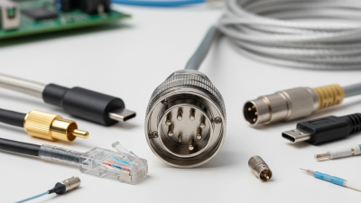
A simple definition is not always enough. The word “pin” can describe different structures across electronics, automotive wiring, industrial controls, and computer hardware. Some pins carry low-voltage data, while others handle substantial current. Their functions must be confirmed through a manufacturer’s datasheet, wiring diagram, or approved service documentation. In practical work, technicians inspect discoloration, bent metal, oxidation, and loose crimping before replacing a connector. These details often reveal the real fault.
Understanding how an Electrical Pin works helps readers choose compatible connectors, interpret pinouts, and avoid unnecessary component damage. It also encourages careful testing with properly rated tools and equipment. Specifications matter. Guessing can be expensive.
Definition and Basic Role of an Electrical Pin
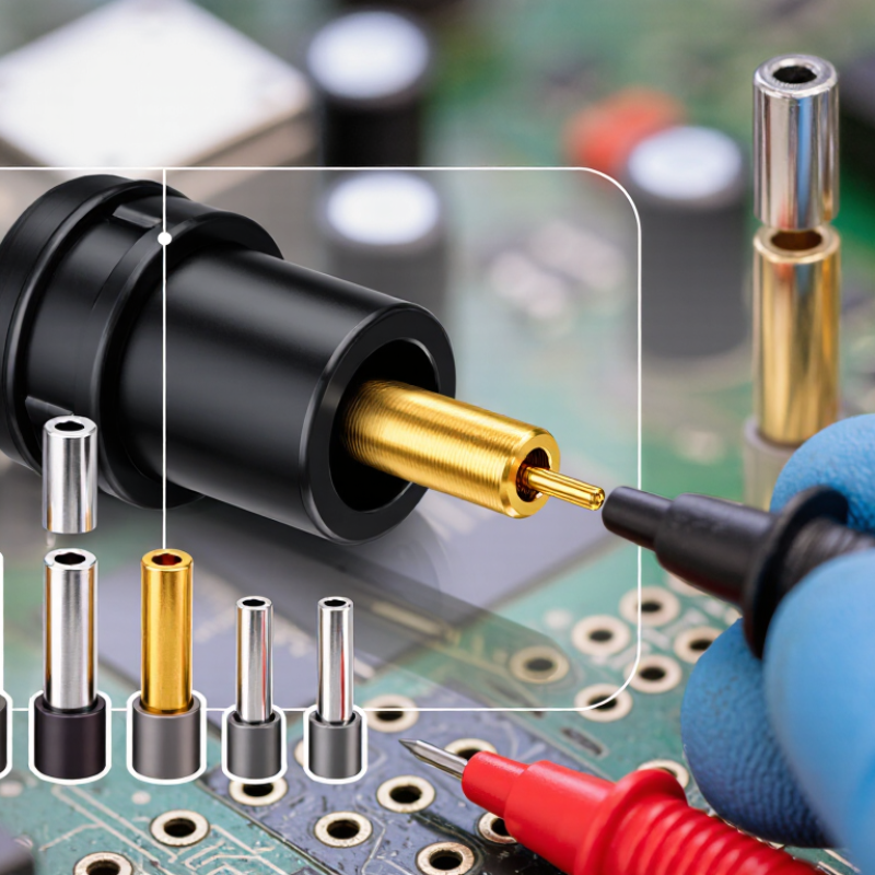
An electrical pin is a small conductive contact that transfers electricity or signals between connected parts. It is usually made from copper or another conductive metal. A protective coating can improve contact stability and reduce surface oxidation. Pins appear in connectors, circuit boards, sockets, switches, and testing equipment.
The pin’s basic role is simple: it creates a controlled electrical path. When a pin enters a matching socket, its metal surface touches another contact. This connection allows current, voltage, or data signals to travel between circuits. Some pins carry power, while others carry ground or low-voltage information. Their shape also supports mechanical alignment, so components connect in the intended position. A loose pin may cause flickering signals, unexpected resistance, or complete failure.
Pin design requires careful attention to size, spacing, pressure, and material. A pin that is too thin may bend during connection. Excessive pressure can damage the socket. During a practical inspection, check for discoloration, looseness, bent metal, and debris. Never assume a pin is safe because it looks clean. I have seen apparently normal contacts perform poorly after repeated insertion. That observation is easy to overlook. Pin numbering also matters, since confusing power and signal positions can damage sensitive circuits. A reliable connection depends on both electrical contact and physical fit.
Main Components and Materials Used in Electrical Pins
An electrical pin is a small conductive part that transfers power or signals between connected circuits. Its main components include the contact tip, conductive shaft, retention section, and insulating housing. The tip touches a socket or mating contact, while the shaft carries current through the connector. A spring feature or slight elastic shape can maintain pressure during vibration. Without stable contact pressure, resistance may rise and produce heat.
Copper alloys are common because they combine good conductivity with useful mechanical strength. Brass offers easy manufacturing, while phosphor bronze provides better spring performance for repeated connections. The surface may receive tin, nickel, or a thin precious-metal coating. These layers reduce oxidation and improve contact reliability. However, thicker plating is not automatically better. Material thickness, temperature, current level, and mating cycles must be evaluated together. A pin can look strong but still fatigue after repeated bending.
Tips: Check the pin’s diameter, insertion force, and rated current. Inspect the contact surface for scratches or discoloration. Keep different metals from creating unwanted corrosion in humid environments. In practical testing, I would measure voltage drop under load rather than trust appearance alone. That detail is easy to miss. Even a clean-looking pin may have weak internal contact or poor alignment. Careful inspection remains necessary, especially in compact assemblies where heat has little room to escape.
How an Electrical Pin Carries Power or Signals
What Is an Electrical Pin and How Does It Work?
An electrical pin is a small conductive contact that transfers power or signals between connected parts. It may sit inside a connector, socket, circuit board, or testing fixture. When two matching contacts meet, the pin creates a controlled path for electric current. Power pins usually carry voltage and current. Signal pins carry changing electrical patterns that represent data, measurements, or control instructions.
A signal pin does more than simply pass electricity. Its voltage may rise, fall, or switch rapidly as information moves through a circuit. A ground pin provides a reference point, helping the system interpret those changes correctly. During a practical inspection, I check alignment, contact pressure, surface condition, and wire attachment. A bent pin can interrupt communication. A loose connection can create heat or unstable readings. My own early mistake was focusing only on voltage and ignoring resistance at the contact point. That produced a misleading result. Small details matter.
Tips
Turn off power before inspecting or servicing a pin. Use a suitable meter and confirm the measurement range first. Keep contacts clean and dry. Do not force a connector into place. Check the pin layout against reliable technical documentation. If a signal behaves strangely, test the ground connection too. It is easy to blame the device. The pin may be the real problem.
Factors That Affect Electrical Pin Performance and Safety
An electrical pin is a conductive contact that carries current between connected parts. It may sit inside a plug, socket, circuit board, or cable assembly. When two pins meet, their contact surfaces create a controlled electrical path. Mechanical pressure keeps that path stable. Small changes matter. A loose fit can increase resistance, heat, and voltage loss.
Pin performance depends on material, shape, plating, and contact force. Copper-based materials conduct well, while protective surface layers can slow corrosion. Excessive current may heat a pin beyond its safe rating. Moisture, dust, vibration, and repeated mating can weaken the connection.
Misalignment may bend the pin or create uneven pressure. In practice, even a carefully designed pin can fail when installation is rushed. That is an uncomfortable detail, but it deserves attention. Engineers should check current capacity, temperature rise, insulation clearance, and mechanical tolerance under realistic conditions.
Tips:
Keep contact surfaces clean and dry. Do not force a misaligned connector. Inspect for discoloration, looseness, bent metal, or cracked insulation. Measure continuity and resistance with suitable equipment before energizing the circuit. Replace damaged parts instead of reshaping them repeatedly. A simple visual check often catches trouble, though it cannot reveal every internal defect. Follow the applicable electrical standard and the manufacturer’s specified ratings.